
Topic 5.5 key terms
- net torque
- The sum of all the torques exerted on a system about one axis, counting counterclockwise as positive and clockwise as negative: .
- rotational equilibrium
- A configuration of torques for which the net torque on a system is zero, ; the system's angular velocity is then constant (zero or not).
- Newton's first law in rotational form
- A system has a constant angular velocity only if the net torque exerted on it is zero.
- rotational corollary to Newton's second law
- If the torques exerted on a rigid system are not balanced, its angular velocity must be changing.
- translational equilibrium
- The net force on a system is zero, so its center of mass moves with constant velocity. It is independent of rotational equilibrium.
- couple
- Two forces of equal magnitude and opposite direction acting along different lines: zero net force but a nonzero net torque.
- static equilibrium
- Both the net force and the net torque are zero and the system is at rest; torques may then be taken about any one axis, usually through an unknown force.
Transcript
3,388 words · 10 parts
The road that rose with a bus on it
At about half past nine on the night of the thirtieth of December, 1952, a red double-decker bus, the number seventy-eight, was rolling across Tower Bridge in London. It was out on the half of the road that lifts when the driver, Albert Gunter, saw the road ahead starting to rise. The bridge was opening underneath him. Somebody at the bridge had made a mistake, and the half of the road he was on was tipping up toward the sky, with a gap opening over the river at its far end.
Gunter decided that stopping would be worse than going, so he put his foot down, and the bus climbed the rising road, jumped the gap, and dropped a few feet onto the other half of the bridge, which was still almost flat. The bus made it, and the next morning’s newspaper quoted Gunter, “I had to keep going, otherwise we would have gone into the water.”
But think about the bridge for a moment. Each half of that road weighs more than a thousand tons, and it lifted with a bus on it, so how do you lift a thousand tons of road? Hidden inside the pier there’s a brick hall twenty-seven meters tall, and as the road swings up, a counterweight of about four hundred tons swings down into it.
The bridge calls each half a bascule, the French word for a seesaw, and that’s exactly what it is, a seesaw the size of a building with a road on one end. By the end of this lesson, you’ll be able to explain how a thousand tons of road can stop halfway up and just hang there, and work out where its counterweight has to sit. So let’s start where the bridge’s engineers started, with the seesaw.
The seesaw under the road
Let’s look at one half of the bridge from the side, straight through the stone. The shaft in the middle is the pivot, the long arm carries the road out over the river, and the short arm carries the counterweight. The bridge doesn’t publish how its weight is spread out, so these are model numbers that fit its real size, with five hundred tons on the river side, twelve meters out, against the counterweight’s four hundred and twenty-two tons.
Now, the bridge’s own website says the counterweight makes the weight on either side of the pivot more or less equal, which is how almost everybody describes a seesaw. But in our model the river side is heavier by almost eighty tons, and the leaf balances anyway. What a seesaw really balances is torque. A force turns something harder the farther from the pivot it acts, so the lighter counterweight sits farther out, about fourteen meters, where its torque exactly matches the river side’s.
Each side twists the leaf with almost sixty million newton-meters, one clockwise and one counterclockwise, so the net torque, which is the sum of all the torques, comes out to zero. Hang on to that equation, because almost every balance problem on the AP exam starts with it.
Let’s tilt the balanced leaf up to forty degrees and hold it there with the brake. When I let go of the brake, what will the leaf do?
And there it stays. It would stay at sixty degrees or at ten just the same, because tilting the leaf shrinks both lever arms by exactly the same fraction. Now I’m going to do something you could never do on the real bridge, which is switch friction off in our model and give the balanced leaf the tiniest nudge. After one tiny nudge, with nothing pushing it and nothing rubbing, what will the leaf do?
Look at that. It doesn’t stop and it doesn’t speed up, it just keeps turning at exactly the rate the nudge gave it, because the torques on it still cancel, so nothing is there to speed it up or slow it down. And here’s the opposite case. If I slide the counterweight in to eleven meters and let go, the leaf doesn’t settle at some new tilt. It swings faster and faster until it slams into the stop, because now the torques don’t cancel.
Balanced doesn’t mean stopped
So a balanced leaf can sit perfectly still or keep turning steadily, and physicists call both of those rotational equilibrium. The condition is that the sum of all the torques, the net torque, is zero.
And what that does to the motion is keep the angular velocity constant, so “rotational equilibrium” and “constant angular velocity” are two ways of saying the same thing. So on a graph of angular velocity against time, the braked leaf is a flat line on zero and the nudged leaf is a flat line above it, and both are rotational equilibrium, because zero is just one of the constants.
Let’s try one. The bridge starts at rest, rises at a steady rate, and then stops at the top. Which graph shows its angular velocity the whole way through?
A real lift looks like this. The leaf starts at rest, speeds up, rises steadily for most of the way, then slows and stops, and the net torque is only nonzero on the two ramps, where the angular velocity is changing. You’ll see this part called a rotational corollary to Newton’s second law. Whenever the torques don’t cancel, the angular velocity has to be changing, so if it’s holding steady, the torques cancel, even while the thing is moving.
The first half of the rule should sound familiar, because it’s Newton’s first law in rotational form. No net force means a constant velocity, and no net torque means a constant angular velocity, whether that’s zero or not.
This is a classic AP question, by the way. They show you something turning at a steady rate and ask for the net torque, and the answer that loses the point is “a torque has to keep it turning,” because the net torque is zero. A lot of us first meet equilibrium in the static case, where everything sits still, but that’s only the zero case, because rotational equilibrium also includes turning at a steady rate.
Drive it yourself
Back on the real bridge, a tall ship is waiting to come through. The real leaf isn’t perfectly balanced, because it’s set up “favouring the riverside by between five to seven tons,” so it always leans a little toward closing. They did that on purpose, because, in the bridge’s words, “this gives the driver better control” of the lift. A leaf that wants to close can never drift open by itself, and the drive only fights that small torque and the friction, never the thousand tons.
In our model, the drive is a lever with three settings. On plus, it twists harder than the trim and the friction put together, the middle setting makes the net torque exactly zero, and minus lets the trim win.
Now you’re the bridge driver. Open the leaf past seventy degrees so the ship can get through, and then bring it to a stop up there.
Here’s how the bridge’s drivers do it on every lift, so look at the flat stretch of this graph. All the way along it, the leaf was rising with zero net torque on it, and that’s what the real bridge’s drive does for most of every lift. And the ship gets through, under a road you’re holding up with zero net torque.
Where the counterweight sits
Now let’s do the engineers’ job properly and work out where the counterweight has to sit. I’ll start with a sketch, the leaf as a line through the pivot with the river on the right, and I’ll call counterclockwise positive. We know the river side’s five hundred tons act twelve meters out, and the counterweight is four hundred and twenty-two tons, so the unknown is d, how far behind the pivot the counterweight sits.
Before I write a single torque, I’ll write down the point I’m taking torques about, the pivot, and use it for every force. That gives us a bonus, because the shaft’s huge push acts right at the pivot, so it has no lever arm and no torque.
Now let’s write the two torques with the leaf tilted at any angle theta. Each lever arm is a distance times cos theta, so the counterweight’s torque is its weight times d cos theta, the river side’s is its weight times x r cos theta, and the two add to zero.
Now watch this. Both terms have a g and a cos theta, so they cancel, and the angle disappears. That’s the algebra behind what you saw on the bridge, because a balance that doesn’t depend on the angle holds at every angle. What’s left says d equals the river side’s mass times its distance, divided by the counterweight’s mass. With our numbers that’s five hundred tons times twelve meters, divided by four hundred and twenty-two tons, which comes to about fourteen point two meters.
Let’s check it. The tons cancel and leave meters, and fourteen point two meters fits inside the real fifteen-meter tail. It makes sense that it’s farther out than twelve, too, because the lighter counterweight needs the longer lever arm.
You try a version. Suppose the engineers could only fit the counterweight ten meters behind the pivot. How heavy would it need to be, in tons, to balance the same river side?
Let’s test the board on the bridge. This model leaf has no trim and no friction, and with the counterweight at fourteen point two meters the needle sits on zero, so when the brake lets go, the leaf just stays where it is. Now let’s bring back the bus from 1952 and park its eight tons thirty-three meters out, near the tip. Its torque adds to the river side’s, so the counterweight has to move farther out. Work out where the counterweight has to sit now, then slide it there and test it with the release button.
The beam the internet argued about
In 2022, an engineering account on Twitter, now X, posted a loaded beam with the words “mechanical reasoning test,” and the post drew more than two thousand replies. Here’s a beam like the one in the post, with thirty pounds hanging six feet left of the support, twenty pounds three feet left, and an unknown X six feet right. The beam is uniform and balanced on its middle, so its own weight acts at the pivot and makes no torque.
Taking torques about the support, the weights on the left turn the beam counterclockwise with thirty times six plus twenty times three, two hundred and forty pound-feet, so X has to match that from six feet away, which makes X forty pounds.
One of the most-liked replies worked it out as thirty plus twenty over two, which also gives forty, because three feet is half of six, so that over-two is really the distance ratio in disguise. Write it without the distances and it falls apart the moment you move the twenty pounds. And the exam will almost always give you newtons and meters, but a balance doesn’t care about units, as long as both sides use the same ones.
Now you take the pen. Slide the twenty pounds out to four and a half feet from the support, with everything else the same. What does X have to be now, in pounds?
Hold the heading
Let’s take all of this up into the air. This helicopter is hovering perfectly still over that painted platform on a mountain lake, and the whole time it’s fighting to keep from spinning. The engine turns the big rotor counterclockwise, seen from above, and the rotor pushes back on the body, so on its own the nose would swing right. The little tail rotor, six meters back, pushes the tail sideways to twist it the other way.
That sideways push would also shove the whole helicopter across the lake, so the pilot tilts the big rotor a touch to push back at the mast. The sideways forces cancel, and because the rotor’s push acts right on the axis, it adds no torque.
The FAA tells pilots there is “an exact amount of tail rotor thrust required to prevent the helicopter from yawing,” which is a pilot’s way of saying the two torques about the mast have to cancel. These two graphs track two separate things, the helicopter’s up-and-down velocity on top and its angular velocity about that vertical axis underneath, and right now both are flat on zero.
Suppose the pilot’s feet push a little too hard, so the tail rotor gives a bit more thrust than it needs, while the pilot’s hands keep the forces on it balanced. What happens to the helicopter?
Now watch what the two graphs do. The velocity stays flat on zero, so it’s in translational equilibrium, but the angular velocity keeps climbing, so it isn’t in rotational equilibrium. So a system can be in one kind of equilibrium without the other, and the exam loves testing exactly that split.
Now the pilot puts the pedals back to trim, and the turning doesn’t stop. The torques cancel again, so the angular velocity holds at whatever rate it had reached. Pilots do this on purpose. It’s called a hovering turn, and the FAA’s handbook tells them to keep “a constant altitude, rate of turn, and rpm,” which is rotational equilibrium while the helicopter is turning.
In real air, the wind on the tail keeps changing how much pedal the pilot needs as the heading swings around, so a real pilot never just returns to trim, but keeps adjusting so that the net torque still comes out to zero. To stop the turn, the pilot needs a torque the other way, so a moment of less tail rotor thrust until the turning stops, and then back to trim.
Now you take the pedals. Turn the helicopter to face the glacier, marked in gold on the compass, and then stop it there so it holds that heading.
It works the other way around, too. When the pilot raises the collective, the lift beats the weight, so the helicopter speeds up as it climbs, but the nose doesn’t move and its angular velocity stays flat on zero.
Notice the pedal readout creeping up, though. More lift takes more power, so the main rotor’s torque grows, and the pilot adds tail rotor thrust to keep the torques cancelling. That’s rotational equilibrium without translational equilibrium.
Now you fly the climb, and this time the pedals are all yours. The collective is about to come up, so keep the nose on its heading all the way up and back to a hover.
Four pushes on a ruler
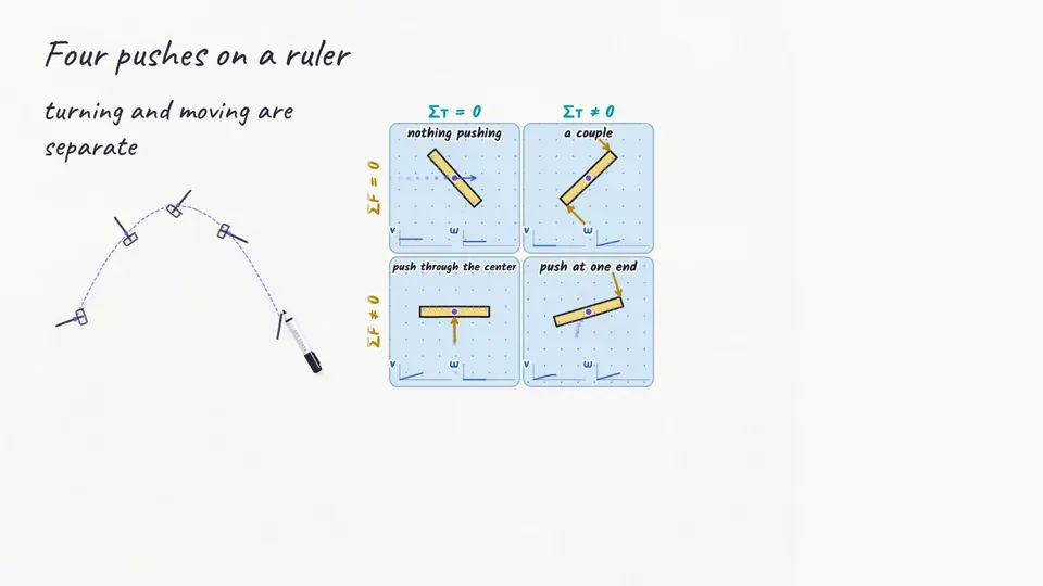
Let’s put the two kinds of equilibrium side by side, with a ruler on frictionless ice, seen from above, pushed four different ways. Watch where each push acts, because that’s what decides the torque. First, a push right through its center. The ruler speeds up across the ice but never starts to spin, because a force through the center of mass has no lever arm about it.
Second, two equal pushes in opposite directions at the two ends. The forces cancel, so the center stays put, but both pushes twist the same way, so the ruler spins faster and faster. So “the forces cancel, so it can’t rotate” is wrong, and this pair, which we call a couple, is the proof. A couple is two equal and opposite forces along different lines, so they cancel as forces but not as torques.
Third, one push at an end, which gives a net force and a net torque, so its center starts to speed up and it starts to spin at the same time. And fourth, nothing at all, so a ruler that was already sliding and spinning keeps doing both. And the helicopter fits right into the grid, with the wrong-pedal hover in the corner where the forces balance and the torques don’t, and the held-heading climb in the corner where the torques balance and the forces don’t.
Here’s a classic exam question about exactly this split. A hammer flips end over end as it flies through the air, and we’ll ignore air resistance. Which of these stays constant during the flight?
The scale isn’t reading the weight
Let’s do one the way the AP exam does it. In 2025, the lab question had a meter stick on a pivot with a spring scale, and one mistake the chief reader called out was saying the scale read the block’s weight “regardless of the block’s position.” Here’s our own version. A uniform meter stick balances on a pivot at its middle, a spring scale holds up the right end, half a meter from the pivot, and a two-hundred-gram block hangs thirty centimeters right of the pivot. What does the scale read?
The stick is in static equilibrium, so you know the routine, and we take torques about the pivot. The stick’s own weight and the pivot’s push both act right at the pivot, so neither makes any torque.
Write the balance and solve it, using ten for g. What does the spring scale read, in newtons? So the scale reads one point two newtons, less than the block’s two newtons of weight, because it acts farther out. It would read the full weight only if the block hung right underneath it.
Look at the shape of that answer, F equals m g R over L. The reading is proportional to R, so twice as far out means twice the reading, and the graph against R is a straight line through the origin. On the 2025 exam, choosing to graph the scale’s force against the block’s distance, which is exactly this relationship, earned a point.
One more skill matters a lot on the exam, and it’s explaining an answer in words. Here’s a prompt about our helicopter, in our model with no drag on the tail. A student says that in a steady hovering turn, the tail rotor must push harder than trim to keep it turning. Do you agree?
A full-credit answer starts with the claim, that you disagree. Then it states the physics, that angular velocity stays constant whenever the net torque is zero. And then it ties that to this helicopter, because in a steady turn the angular velocity is constant, so the tail rotor only has to cancel the main rotor’s torque, which is exactly trim. That last part is the sentence that earns the point.
Vague answers lose it. “I disagree because it’s balanced” never says what’s balanced, and “because of Newton’s first law” names a law without connecting it to this helicopter, and that connection is exactly what the readers look for.
Back on the bridge, the leaf is rising at a steady rate, and a student says the drive must exert a net torque on it to keep it rising. Which response earns full credit?
Five for me, and five for the missus
Let’s go back to that night in 1952 and watch it again, with everything you know now. The leaf was balanced and trimmed, so the drive only had to deal with the trim, the friction, and a bus rolling out toward the tip, whose torque in our model grew to about the size of the trim’s.
Now park the bus near the tip and let the drive lift the leaf again. Whenever the leaf rises at a steady rate, the net torque on it is zero, bus and all. Gunter got ten pounds and a day off, and he said he’d split it, “Five for me, and five for the missus.”
The whole lesson fits on one board. A seesaw balances when the torques about the pivot cancel, even when the weights don’t match. That’s rotational equilibrium, and it means the angular velocity is constant, whether the thing is sitting still or turning steadily. When the torques don’t cancel, the angular velocity must be changing, like at the start and end of every lift.
Turning and moving are separate questions, so the forces and the torques each get their own check. And in every problem, choose your pivot and write it down, and remember that the forces through it stay on the diagram but make no torque. Next time we’ll take on the question this lesson kept stepping around, which is how fast the angular velocity changes when the torques don’t cancel.